Rhombotron
We will continue this pattern until we have reached the Infinite Everything
Debrief
The Challenge
1/ Explore the reflective possibilities of a new polyhedron — the rhombic dodecahedron
2/ Address the production and quality issues with my Octahedral Infinity Mirror
Process & Iteration
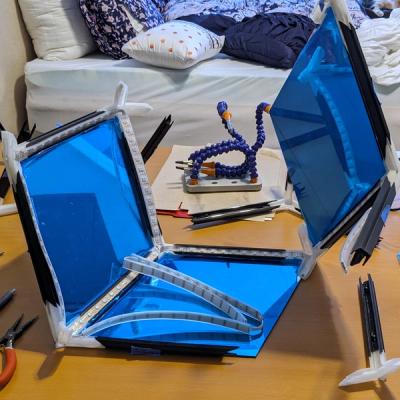
Rhombotron is the evolution of my octahedral infinity mirror with new geometry and a professional finish. When I started building the octahedron, I had envisioned the end product but overlooked many important details of the design, including:
- A way to attach the LED strips along the edges
- A strain-proof way to route the cabling for power and data to the exterior
- An enclosure for the microcontroller
- A way to install the last half-mirrored acrylic panel — which was extremely difficult when all the others were in place!
Additionally, after seeing the octahedron in action, I realized the interior reflections looked about the same from every perspective. The LEDs around each triangular panel were simply reflected in perfect opposition by the mirrors on opposing sides, resulting in a nested series of hexagons. Sure, the layered reflections shifted as you moved around it in an interesting, parallax fashion, but that was its full range. I instantly began to wonder about the effects possible with a different polyhedron.
I was struck by the rhombic dodecahedron, a variant of the more well-known regular dodecahedron (d12) faces are rhombuses instead of pentagons. Like the octahedron and its dual, the cube, the rhombic dodecahedron has octahedral symmetry, with three fourfold axes of symmetry, four threefold axes, and six twofold axes. However, unlike those polyhedra, in which every vertex connects to either 3 or 4 edges (respectively), the rhombic dodecahedron has both.
What all of this means is there are 3 unique perspectives:

I needed to see how the asymmetry of the rhombic faces affected the patterns of the internal reflections!
Getting Started
When I started this project, I had been using OpenSCAD for most of my 3D modeling work. My first step was to make the basic, solid polyhedron.
Rather than write out the formulas to precisely calculate the vertex coordinates of a normalized-scale rhombic dodecahedron, I took a slightly lazier approach. If you spend enough time researching polyhedra online, you'll eventually stumble across George W. Hart's incredible website on these fascinating geometric objects. His page has an incredible range of 3D-rendered polyhedra, and he freely provides VRML files (a blast from the past!) for many of them. From his rhombic dodecahedron file, I was able to extract the coordinates and line and face sets I needed. Seriously, if you appreciate the intersection of art and math as much as I do, you will love getting lost in George's site!
I didn't get very far using raw OpenSCAD before I pivoted to SolidPython, a python wrapper that renders compliant SCAD code. I created a class to store the pre-calculated unit-scale coordinates and initialized it with a given edge length — knowing I was going to stuff 5 meters of LEDs inside and thus needed the edges to be at least 208 mm long. This class served as the core of the modeling effort, and I iterated on it throughout the project.
class RhombicDodecahedron(object):
    """A convex polyhedron with 12 congruent rhombic faces"""

    base_vertices = [
        [-0.5, 0.7071068, 0.8660254],
        [-0.5, -0.3535534, 0.8660254],
        [0.5, -0.7071068, 0.8660254],
        [0.5, 0.3535534, 0.8660254],
        [1.0, 0.7071068, 0],
        [0, 1.06066, 0],
        [-1.0, 0.3535534, 0],
        [-1.0, -0.7071068, 0],
        [0, -1.06066, 0],
        [1.0, -0.3535534, 0],
        [0.5, -0.7071068, -0.8660254],
        [0.5, 0.3535534, -0.8660254],
        [-0.5, 0.7071068, -0.8660254],
        [-0.5, -0.3535534, -0.8660254],
    ]

    base_edge_length = np.linalg.norm(np.array(base_vertices[0]) - np.array(base_vertices[1]))

    def __init__(self, edge_length=1):
        self._edge_length = edge_length

    @property
    def vertices(self):
        return [
            [
                v * self.edge_length / RhombicDodecahedron.base_edge_length
                for v in vertex
            ]
            for vertex in RhombicDodecahedron.base_vertices
        ]
Modeling the Rhombotron
This class served as the foundation of the modeling effort, and I continued iterating on it throughout the project. First, I added a method to render arbitrary shapes at each vertex and combine them into edges with `hull()` operations. This enabled me to render essentially a wireframe rhombic dodecahedron, which I of course immediately 3D printed to behold IRL.
    def render_vertex(self, vertex=0, **kwargs):
        vertex_geom = kwargs.pop("vertex_geom", sphere(self.edge_length / 10))
        col = {"c": kwargs.pop("color", None), "alpha": kwargs.pop("alpha", 1.0)}

        return color(**col)(translate(self.vertices[vertex])(vertex_geom))

    def render_edge(self, edge=[2, 8], **kwargs):
        col = {"c": kwargs.pop("color", None), "alpha": kwargs.pop("alpha", 1.0)}

        rendered = hull()([self.render_vertex(vertex=v, **kwargs) for v in edge])

        return color(**col)(rendered)
The next challenge was making channels for the LEDs, wiring, and acrylic panels. Thankfully, this is an area where SolidPython really shines, as it provides a `hole()` function that allows you to mark objects as first-priority holes in the component. I used this to add support for optional parameters for geometry I wanted to use as cutters in the vertices and edges:
def render_edge(self, edge=[2, 8], **kwargs):
col = {"c": kwargs.pop("color", None), "alpha": kwargs.pop("alpha", 1.0)}
vertex_cutout = kwargs.pop("vertex_cutout", None)
edge_cutout = kwargs.pop("edge_cutout", None)
face_cutout = kwargs.pop("face_cutout", False)
rendered = hull()([self.render_vertex(vertex=v, **kwargs) for v in edge])
# Orient 3 to 4
if edge_cutout is not None:
tri_vertex = [
vertex for vertex in edge if self.vertex_order(vertex=vertex) == 3
][0]
quad_vertex = [
vertex for vertex in edge if self.vertex_order(vertex=vertex) == 4
][0]
rendered += hole()(
multmatrix(
m=utils.transform_between(
self.vertices[tri_vertex], self.vertices[quad_vertex]
)
)(edge_cutout)
)
if face_cutout:
rendered += color("red")(
hole()(
[
self.render_face(face, **kwargs)
for face in RhombicDodecahedron.base_faces
if set(edge).issubset(face)
]
)
)
if vertex_cutout is not None:
rendered += hole()(
[
translate(self.vertices[v])(
rotate(**utils.rotate_between(up_vector, self.vertices[v]))(
vertex_cutout
)
)
for v in edge
]
)
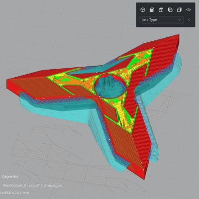
return color(**col)(rendered)The frame was much too big to print in one piece on my Ender-3, so I cut it into three components: a 3-order vertex, a 4-order vertex, and an edge. Printing enough of each type (8, 6, and 24, respectively) would give me a complete Rhombotron. Recalling the difficulty I had assembling the octahedron from its minimal parts, I decided to design pocket holes and screw the components together:

Special Components
The octahedron also heavily informed my development of modified versions of some parts to solve specific problems. First, the lack of proper strain relief allowed it to fail twice soon after I finished assembling it. To that end, I modified one of the 4-order vertices with a hole for securing a DC barrel jack to supply power.

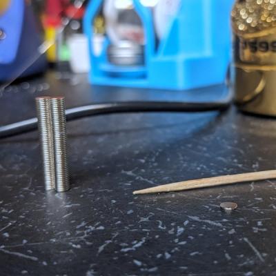
Additionally, I'd also learned that actually quite hard to install the last acrylic panel in one of these. At that point, all of the edges that will enclose it are tightly locked into their final position from installing the other panels. Loosening them to give clearance for the last panel allows other panels to slip out, moving the problem elsewhere. I needed a way to easily insert and secure the last panel and eventually decided on a removable design using neodymium magnets.
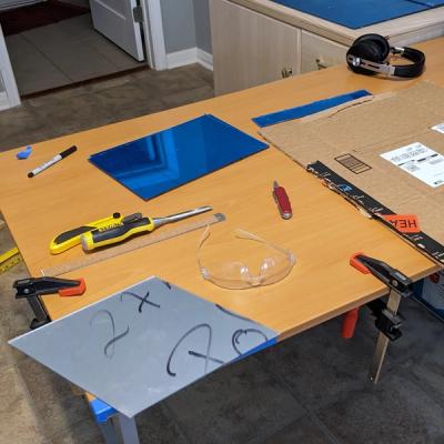
To make it look clean, I needed to split the parts I had designed to create two parts, and then create small recessions to glue the magnets into. However, thinking about how to split the edges and vertices around the panel using OpenSCAD/SolidPython hurt my brain. I decided to move the modeling process into Blender and use the knife tool to carefully cut each model in an upper and lower half. The upper half would form a sort of frame and be glued in place on a face panel. It would then magnetically attach to its lower part, installed on the Rhombotron body.

Electronics and Wiring
In parallel with the modeling, I began to think more deeply about the electronics. At 312 5v LEDs, the Rhombotron would have more than twice as many LEDs to power than the octahedron. While I got away with powering that from just one end of the LED strand, I knew voltage drop was a real likelihood for the Rhombotron. I decided injecting power at three points along the strand would ensure a robust and even supply of juice, even at full brightness. Speaking of that, I estimated the device would be capable of drawing about 19A at 5V according to the 60 mA-per-LED rule of thumb. I was looking at a 20 – 25A 5V power supply unit, which is getting into OEM component range ($$).
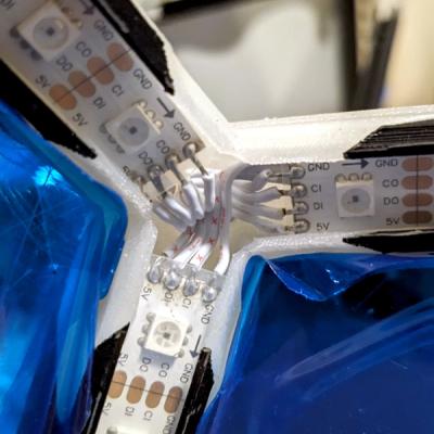
There was a final wrinkle that impacted the electronics design. Each edge holds a segment of LEDs that need to be connected end to end in a complete circuit. The segments need to snake around the polyhedron, tracing every edge once while starting and ending at the same point (the DC jack). I stared at my pilot-scale model for quite a while, tracing possible paths with my eyes and fingers before eventually realizing this was a graph theory question. As it turns out, the rhombic dodecahedron is non-Hamiltonian and non-Eulerian — that is, there is no way to visit each vertex exactly once and start and end at the same vertex. Fun!
As I educated myself on graph theory basics, I realized I needed a way to make it a Eulerian graph. I also discovered the NetworkX module includes a `eulerize` function that does exactly that. I fed in the set of edges (starting and ending vertex pairs) and out popped a sequence starting and ending at the DC barrel jack vertex while necessarily doubling back along a couple of the edges. This enabled me to easily supply power to the complete strand at both ends as well as roughly in the middle, in addition to the microcontroller that drives the LED effects, right where the power enters the frame.
{SolidPython preview of the path on a wireframe or text block showing the final result}
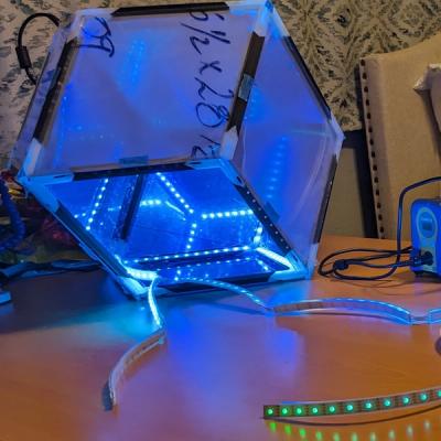
To drive the LEDs, I decided to try a PixelBlaze V3 Pico, which I'd learned about from Evil Genius Labs. Its tiny footprint meant I could solder it beneath the first segment, snug inside the silicone jacket and completely hidden inside the Rhombotron. Additionally, its thoughtful features enabled me to easily manage patterns and configurations wirelessly, as well as load a 3D map of the LEDs to use in patterns.
Bill of Materials
Here is a brief list of the electronics parts I used:
- PixelBlaze V3 Pico
- 5m+ 60 LED/m APA102 IP67 white PCB
- 5V 20A Meanwell LRS-200-5 power supply unit
- OpenBuilds PowerCase PSU enclosure and terminal block
- 1000 µF 6.3V capacitor
- 4-conductor white cable (for connecting segments)
LED Mapping
Mapping was fairly straightforward. I just needed to compute the approximate 3D coordinates of each LED along every edge. I experimented with rotating the coordinates in 3D space to align the shape with the PixelBlaze axes, as well as different ways of sorting the LED coordinates. I think I finally settled on `rhombotron_3d_map_squared.json`, but it was interesting to see how the different maps affected the patterns.
import numpy as np
from scipy.spatial.transform import Rotation as R

led_strip_length = 240 # 240 mm
rhombotron = RhombicDodecahedron(edge_length=led_strip_length)

led_count = 13 # per edge
led_coords = []
for edge in rhombotron.base_edges:
    start = np.array(rhombotron.vertices[edge[0]])
    end = np.array(rhombotron.vertices[edge[1]])
    edge_vector = end - start

    led_margin = 15 # inset from edge extents
    led_spacing = 17.5 # on center
    for i in range(led_count):
        temp = list(start + ((led_margin + led_spacing * i) / led_strip_length) * edge_vector)
        led_coords.append(temp)

print(led_coords, file=open("./designs/rhombotron/rhombotron_3d_map.json", "w"))

# rotate so the top/bottom rhombus diagonals are aligned with X and Y axes
r = R.from_rotvec([0, 0, -0.6154797087 + np.pi / 2])
led_coords = r.apply(led_coords).tolist()
print(led_coords, file=open("./designs/rhombotron/rhombotron_3d_map_squared.json", "w"))

# sort by vertical position (z coordinate)
led_coords.sort(key=lambda x: x[2])
print(led_coords, file=open("./designs/rhombotron/rhombotron_3d_map_z_sorted.json", "w"))

# sort by distance from origin
led_coords.sort(key=lambda x: np.array(x).size)
print(led_coords, file=open("./designs/rhombotron/rhombotron_3d_map_origin_sorted.json", "w"))
The Outcome
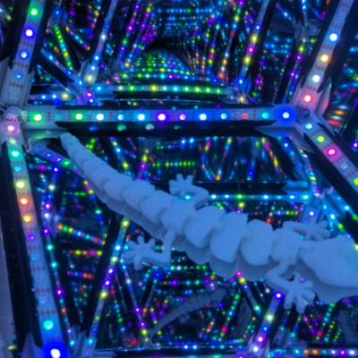
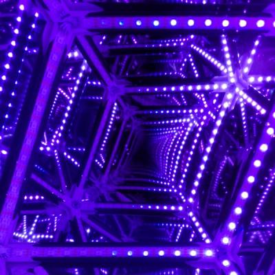
Ultimately, the project was a success! The new design produced a precise, minimalist frame. Nonetheless, the miniature PixelBlaze V3 Pico manages to hide within one of the edges. After mapping the LEDs and tuning the patterns, I have a beautiful, fascinating luminary.
Key Learnings
- Deeper appreciation and knowledge of geometry and graph theory
- Extensive python class development with `@classmethod` and `@property` members
- Complex knife edits with Blender
- PixelBlaze LED mapping and pattern development
Gallery